Building fire smoke exhaust systems are critical facilities to ensure the safety of personnel evacuation during a fire. As a core component of such systems, the design and construction of smoke exhaust ducts must strictly comply with current national technical standards and specifications. The following are the core points summarized based on relevant specifications:
1. Design Standards and Material Selection
The design of smoke exhaust ducts must first meet the fire resistance rating requirements. Ducts must be made of non-combustible materials, and their inner walls must be kept smooth to reduce smoke exhaust resistance. Galvanized steel sheet is a commonly used basic material. When ducts need to pass through fire separation components such as fire-resistant partition walls and floors, the ducts themselves or their outer walls must take additional fire protection measures to meet the same fire resistance rating requirements as the separation components at that location. For example, the partition walls of stairwells and antechambers require a fire resistance rating of not less than 2.0 hours, and floors require 1.5 hours or 1.0 hour.
To achieve a higher fire resistance rating, the mainstream solution is to apply fireproof cladding to metal ducts. The cladding material must be Class A non-combustible material and possess properties such as high-temperature resistance, thermal insulation, sound absorption, and sound insulation. Glass wool, rock wool, etc., are commonly used cladding materials.
2. System Layout and Installation Requirements
Smoke exhaust outlets should be arranged close to potential smoke sources to quickly and effectively capture and exhaust smoke. The laying direction, height of the pipes, and the distance from the automatic sprinkler system must comply with technical regulations. It is worth noting that civil engineering air ducts should not be used as smoke exhaust ducts.
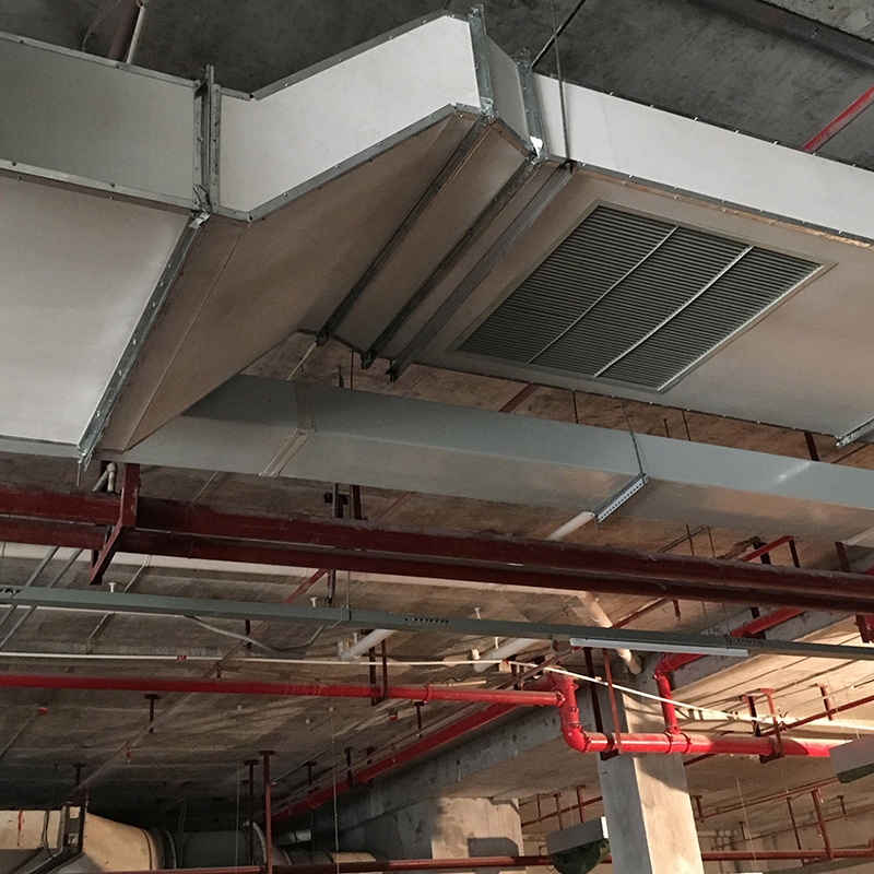
During installation, if a cladding method combining insulation boards and fireproof boards is adopted, strict processes must be followed. For example, the joints of insulation boards must be sealed with special tape, and metal brackets must be installed to fix the outer fireproof boards to ensure the integrity and stability of the fireproof structure. All construction must not affect the normal operation of components such as air valves.
3. Regulations on Applicable Places
According to mandatory specifications, mechanical smoke exhaust facilities must be installed in places such as atriums in multi-storey civil buildings, singing and dancing entertainment, film screening, and amusement venues, specific sizes of underground rooms, and internal corridors with a length exceeding 20 meters. For areas such as smoke-proof stairwells and their antechambers, and fire elevator antechambers, smoke-proof facilities must be installed.
4. Fire Resistance Rating and Construction Details
When ducts pass through fire-resistant partition walls, floors, and firewalls, the fire dampers on the ducts at the penetration points and the ducts within 2 meters on both sides of the smoke exhaust fire dampers should use fire-resistant ducts or the outer walls of the ducts should take fire protection measures, and the fire resistance rating should not be lower than that of the fire separation component. Ducts with a fire resistance rating exceeding 1 hour usually need to be wrapped with additional fireproof boards.
During construction, insulation boards should be laid from bottom to top and connected to each other, and the joints must be sealed with insulation tape. Fireproof boards must be fixed with metal brackets to ensure neat joints and not affect the operation of duct components.
In conclusion, the smoke exhaust duct system is a comprehensive project involving materials science, structural mechanics, and fire protection science. Its design and implementation must strictly align with the latest technical specifications to ensure its reliability and effectiveness in a fire. Following the above points can not only improve the performance of the smoke exhaust system but also provide a solid guarantee for building safety.